Configure BGP and BGP Routing Policy
Objective
This guide provides instructions to configure Border Gateway Protocol (BGP) and BGP routing policies for your Customer Edge (CE) Site deployments.
Support Modes
F5 provides BGP support for your CE to enable seamless integration and interoperability with third-party networking and security gateways. BGP can operate in two modes:
-
Directly over Ethernet: BGP runs on an Ethernet interface when the CE and the peer device are on the same subnet or reachable across a Layer 3 network.
-
Over IPsec VPN: BGP can also be established on top of IPsec VPN tunnels, as part of the new External Connector functionality.
Prerequisites
-
A valid account. If you do not have an account, see Getting Started with Console.
-
One or more registered CE sites in your tenant. To deploy a CE Site, see the Customer Edge Deployment guides.
-
Ensure you are on the latest CRT version for latest available features. See the official releases notes guide for more information. To upgrade your CE, see the Manage CE Site guide.
BGP Peering
In the configuration form, the first three configuration sections (Metadata, Where, and Parameters) reference the individual CE Site. All peers are defined under the Peers section.
The configuration process consists of two main steps:
-
Defining the BGP parameters of the CE Site. This step involves the name, Autonomous System Number (ASN), and BGP Router ID of your CE Site. This step is performed once for your CE Site.
-
Defining the BGP peers: This step involves adding the BGP peer and can happen one or more times on a CE Site. Therefore, you perform this step every time you need to add a new BGP peer.
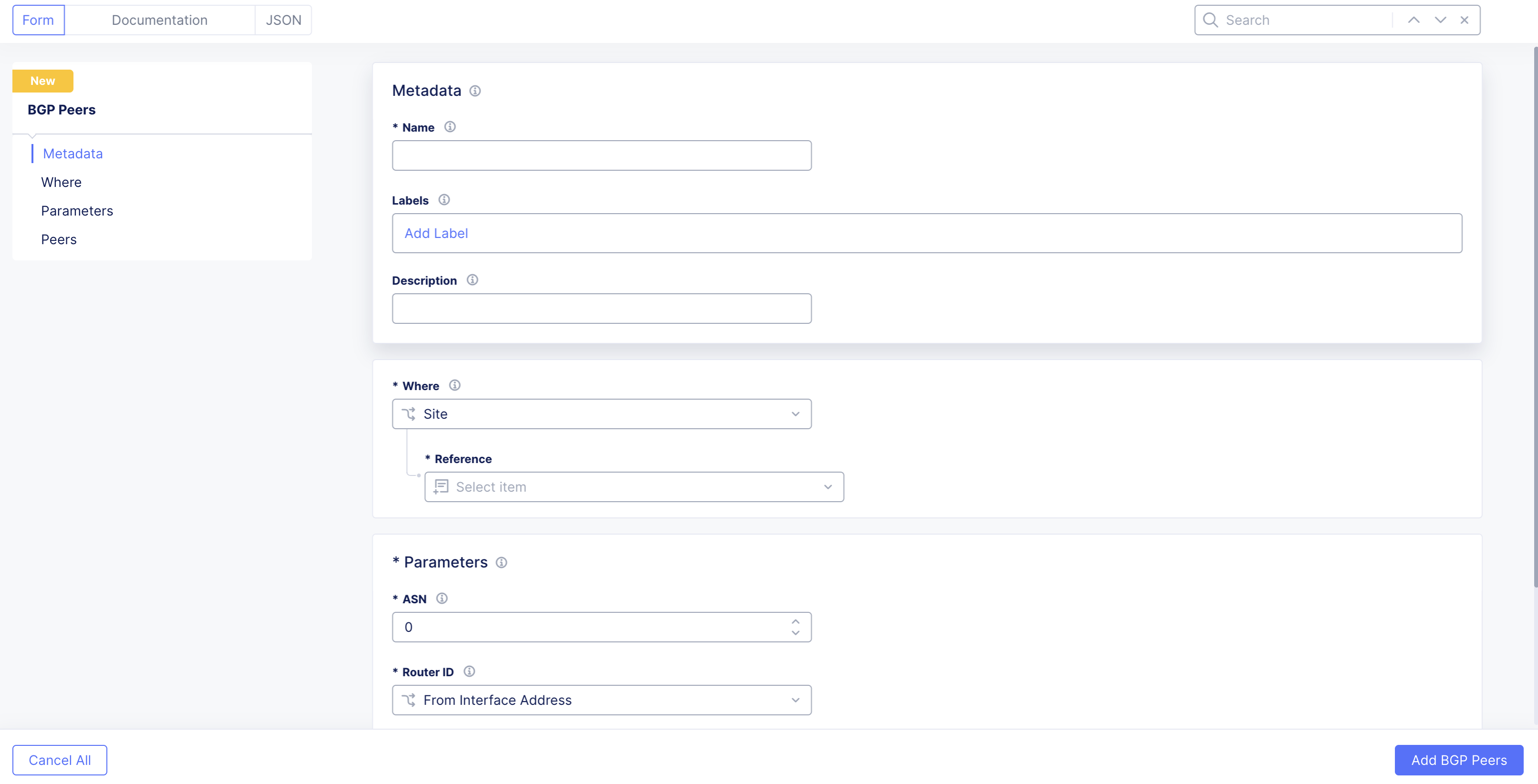
Figure: Configuration Form
Metadata
-
Name: When providing a name, F5 recommends that you reference the "site-name-bgp-config". This is useful because you can include all BGP configurations for your CE Site in a single view. For example: If you have a Site named aws-site, then you can provide a name of aws-site-bgp-config.
-
Labels: Provides help to organize and categorize objects as per your preferences. Labels are not mandatory.
-
Description: Provides useful information to share additional context on the configuration.
Where
-
Where: Presents a choice for Site or Virtual Site. Virtual Site. In the context of Distributed Cloud Services, this allows configurations to span multiple CE sites at once.
-
Reference: Based on the selection of Site or Virtual Site. Reference shows the available CE sites or virtual sites.
Parameters
- ASN: This option sets the Autonomous System Number (ASN) of your CE Site or virtual site that you selected.
- Router ID: This option can be set to:
- From Interface Address: This option selects the router ID based on the interface address of each CE node. The router ID will be set to the interface with the highest address. This is the default and recommended option.
- From Site: In this case, Distributed Cloud automatically selects the router ID. This is not a recommended option and might be removed in future versions.
- IP Address: This is only possible with a single-node CE to choose the router ID address. For three-node CEs, this option does not work as it provides a common router ID for all nodes of a CE Site.
Add BGP Peer
In this section, you create and define the BGP peers. You can repeat this process multiple times on a CE Site, depending on your architecture requirements. You can get to this process initially as part of BGP configuration, or you can get to it at a later stage to add additional peers.
Step 1: Create BGP peer object.
- Navigate to Multi-Cloud Network Connect > Manage > Networking > BGP Peers and Policies.
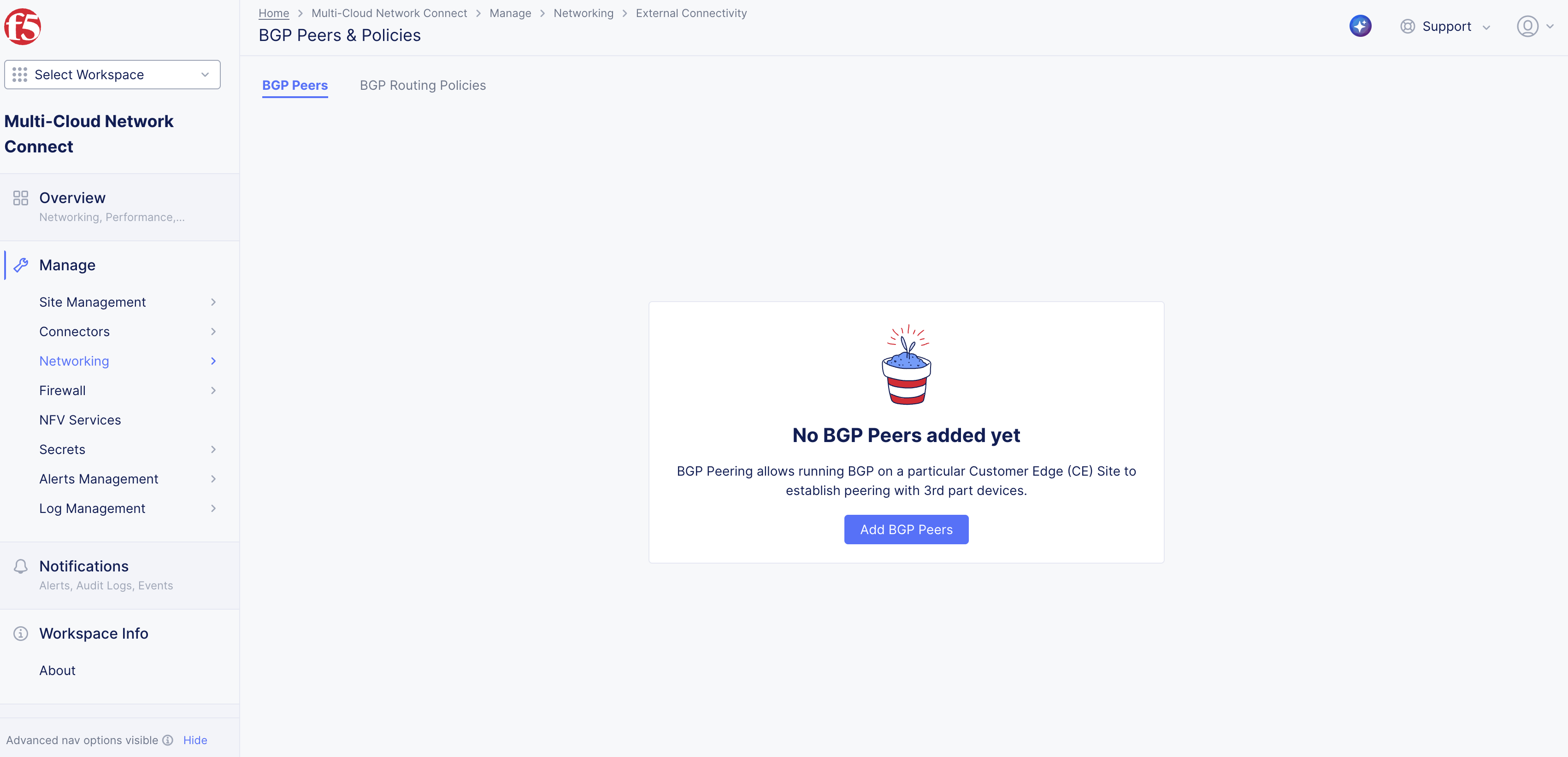
Figure: Add Peer
-
Select the BGP Peers tab. Click Add BGP Peer.
-
Enter a name and description. See the Metadata section above for more information on the options available.
-
From the Where menu, select the CE Site used as the BGP peer. You can choose a CE Site or virtual site. See the Where section above for more information on the options available.
Step 2: Configure BGP peer parameters.
-
In the ASN field, enter the ASN used for your CE Site or virtual site.
-
From the Router ID menu, select an option. See the Parameters' section above for more information on the options available.
Step 3: Add BGP peer(s).
Under the Peers section, you can one or more peers for your CE Site or virtual site.
- Click Add Item.
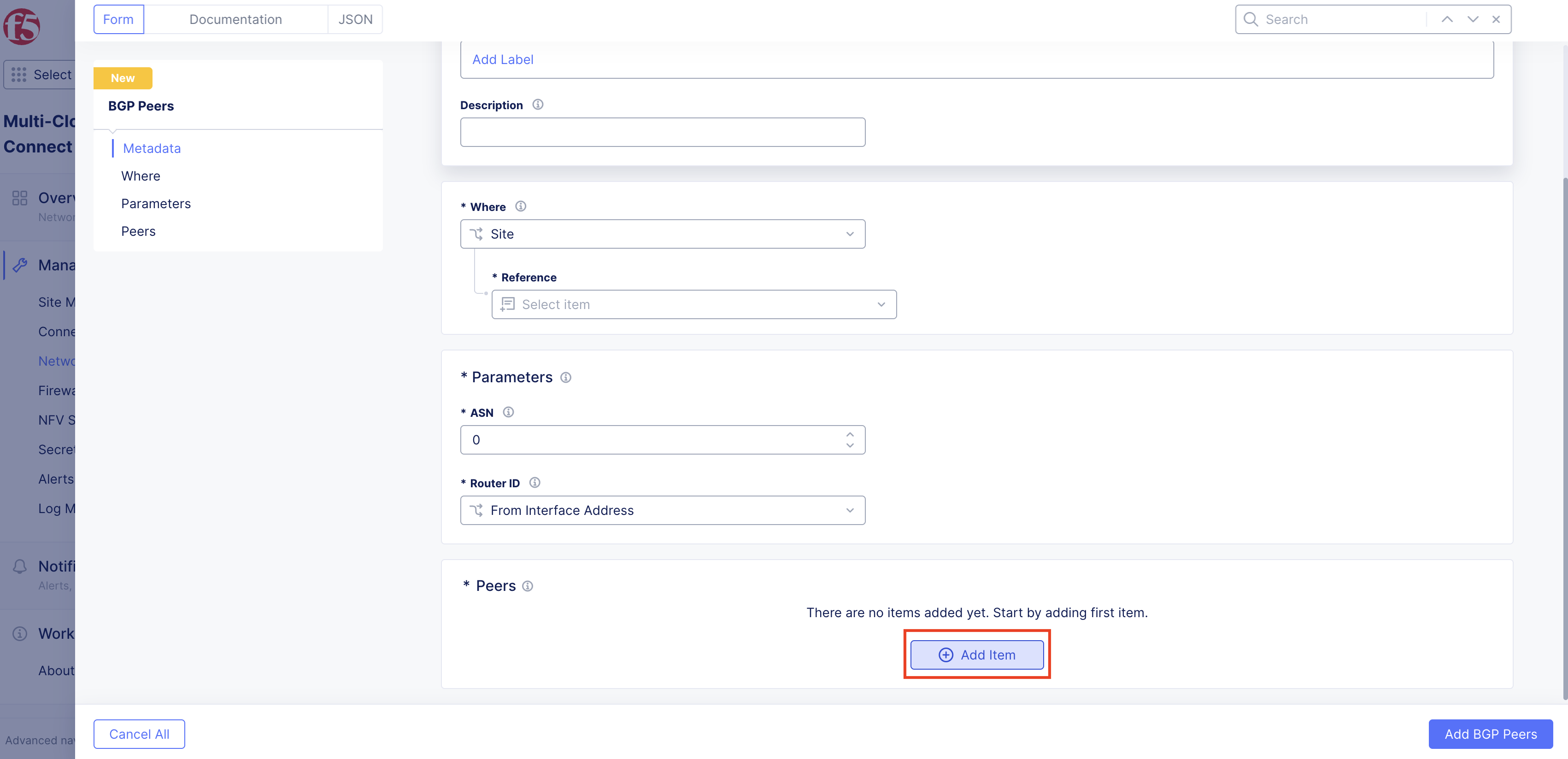
Figure: Add Item
-
In the configuration form, perform the following:
-
In the Name, specify a name for the peer. F5 recommends you use distinguished names so that you can identify the peer directly.
-
Optionally, add additional context in the Description field.
-
For Peer Type, no need to select any option as only External (eBGP peering) is selected.
-
For ASN, select the ASN of the BGP peer.
-
For Peer Address, select the recommended option Peer Address and then set it manually. The other options Offset from beginning, Offset from End of Subnet, Address from Site Object, and Default Gateway are meant to infer the BGP peer address. External Connector Peer is used when you want to establish a BGP peering over an External Connector. Disable can be used when you do not want to establish IPv4 peering.
-
For Peer IPv6 Address, use the same pattern and choice as Peer Address for Distributed Cloud tenants that have enabled IPv6.
-
For Peer Port, enter the TCP port number over which BGP is running on the peer. By default, and for most implementations, this is TCP port 179.
-
For Family IPv4 Unicast, use this setting to enable or disable the IPv4 exchange of routes with the BGP peer (AFI 1 and SAFI 1).
-
Optionally, configure peer aggregation prefixes under Configure BGP Aggregation. Click Add Item. This enhancement allows advertising a BGP aggregate route to all BGP peers, either with or without the more specific routes that make up the aggregate. The aggregate route is automatically withdrawn when all of its constituent routes become invalid. Though aggregation is configured per peer, its effect will apply to all peers. Aggregation in BGP occurs only when more specific routes exist in the routing tables and applies to outbound routing advertisement. For this feature, ensure that you are on version crt-20251001-0189. See the official releases notes guide for more information.
-
For Family IPv6 Unicast, use this setting to enable or disable the IPv6 exchange of routes with the BGP peer (AFI 2 and SAFI 1).
-
For Peer interface(s), use this to set the Interface or Interface List on the CE nodes over which the peering is happening. Interface List allows selecting more than one interface. Note that for External Connector it is referenced as a single interface even if multiple nodes are participating.
-
For BGP Authentication, use this to disable authentication with No Authentication or to authenticate with the MD5 Authentication Key and specifying it.
-
For Passive Mode, use this option to enable your CE nodes to listen to BGP messages on the specified Peer Interface or Interface list but not initiate toward the BGP peer. If you disable this option, your CE nodes will initiate the BGP exchange with the remote peer on the Peer interface or Interface list.
-
Optionally, add a Label to provide additional context for the peer.
-
For BGP Routing Policy, use this setting to enable or disable BGP routing policy on your CE toward a particular peer. The default option is to disable BGP routing policy. Note that this is a new functionality introduced in CRT version crt-20250701-0198.
-
Optionally, from the BFD menu, choose to enable Bi-directional Forwarding Detection (BFD) for your BGP peer neighbors. By default, this option is disabled. When enabled, this helps detect link and path failures for your BGP peer and its neighbors. You also have the option to change the default settings for the following:
- Transmit Interval: This is the minimum amount of time (typically in milliseconds) the local system wants to wait between sending its own BFD control packets. Transmit interval is in milliseconds. Minimum timer supported is 300 milliseconds.
- Minimum Receive Interval: This is the minimum time interval at which the local system is capable of receiving and processing BFD control packets from its peer. Receive interval is in milliseconds. Minimum timer supported is 300 milliseconds.
- Multiplier: This is the grace period (number of missed packets) before failing. Minimum BFD multiplier is 2.
-
Important: Ensure that you are on version crt-20251001-0189. See the official releases notes guide for more information.
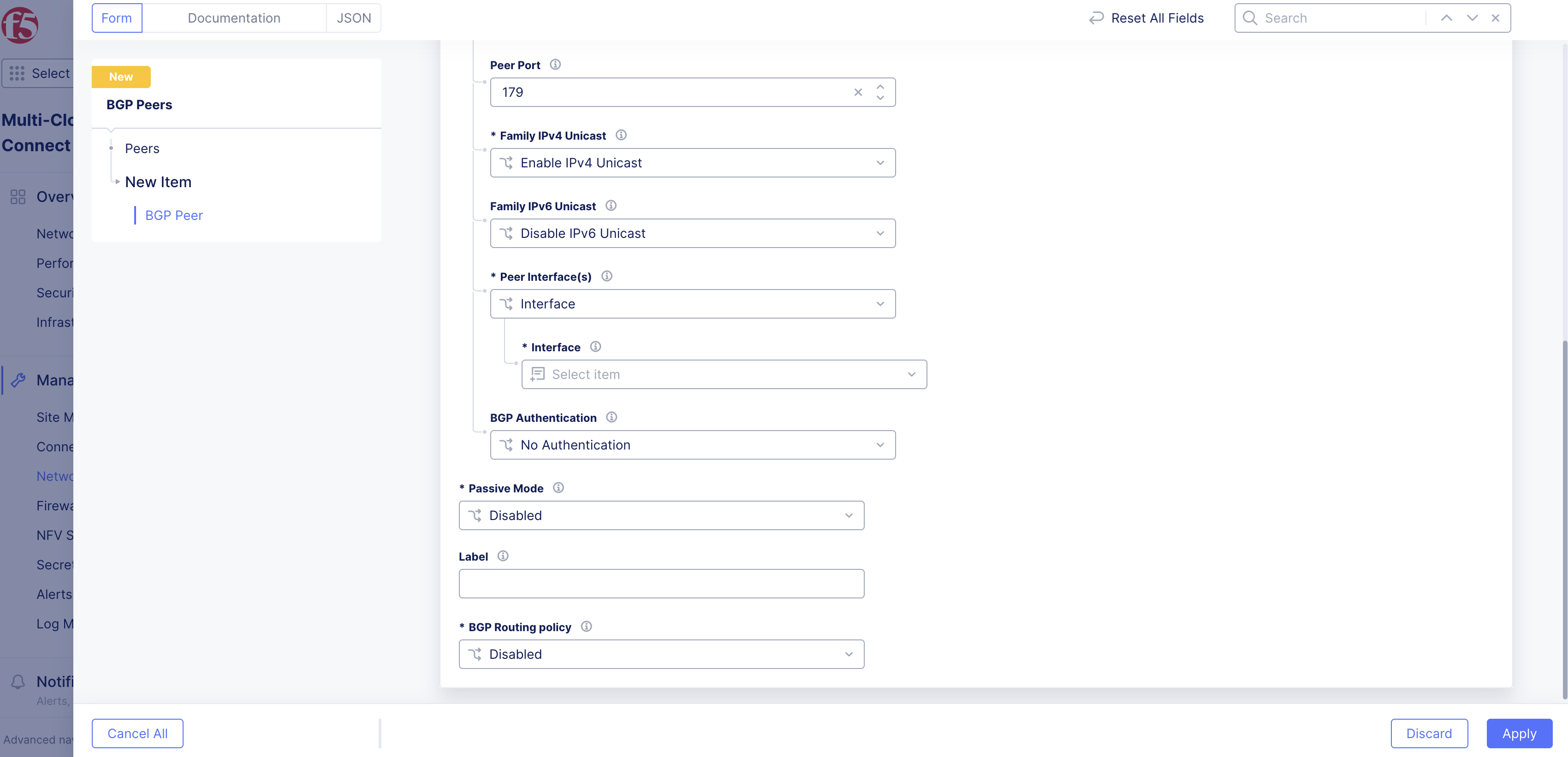
Figure: Peer Configuration
BGP Routing Policies
This functionality enables inbound and outbound route filtering as well as traffic engineering using BGP attributes, such as local preference, AS path prepending, and Multi-Exit Discriminator (MED).
This is a new functionality introduced in CRT version crt-20250701-0198.
Best Practices
BGP routing policies are applied in the context of a particular BGP peer. You can still configure the policies in one of two ways, depending on the intent and scenario:
-
Configure a single BGP routing policy per CE Site and apply it across all peerings. This scenario make sense for when you want to filter a particular route from all your BGP peers.
-
Configure a single BGP routing policy per BGP neighbor. This scenario is required when you have different intents from different neighbors.
You can apply the BGP routing policies for your CE Site or for nodes within your CE Site, allowing you to perform BGP route manipulation within the CE Site.
Routing Policy Scenarios
- Basic topology: The CE Site named ce-site-1 has a prefix of 10.1.1.0/24 and is connecting to two routers, R1 and R2, over a shared subnet 172.16.1.0/24. R1 and R2 also share the subnets 10.10.10.0/24 and 10.10.11.0/24.
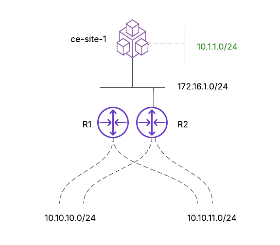
Figure: Basic Topology
- Inbound route filtering: The objective, as shown, is to accept only the 10.10.10.0/24 prefix from the neighboring routers, R1 and R2.
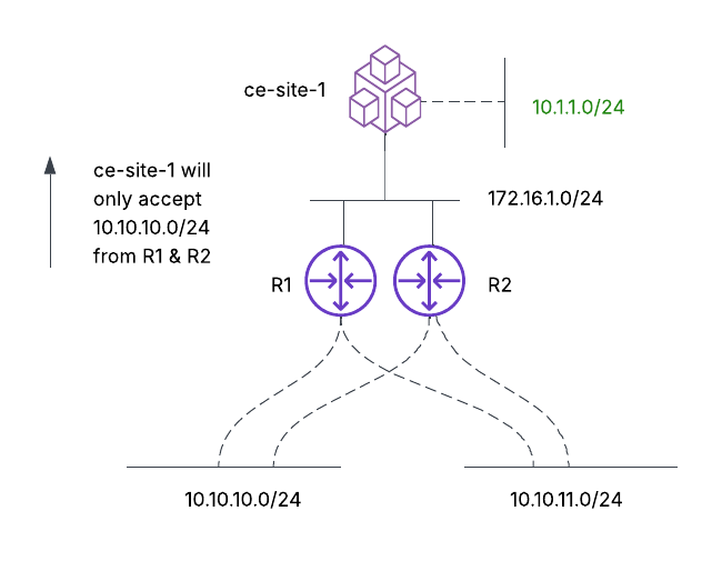
Figure: Inbound Route Filtering
- Outbound route filtering: The objective is for the ce-site-1 to advertise 10.1.1.0/24 to R1 only and not to R2. Note that without any intervention, the CE will automatically advertise 10.1.1.0/24 to both R1 and R2. Notice that post-applying the outbound route filtering on ce-site-1 only R1 knows the route to 10.1.1.0/24.
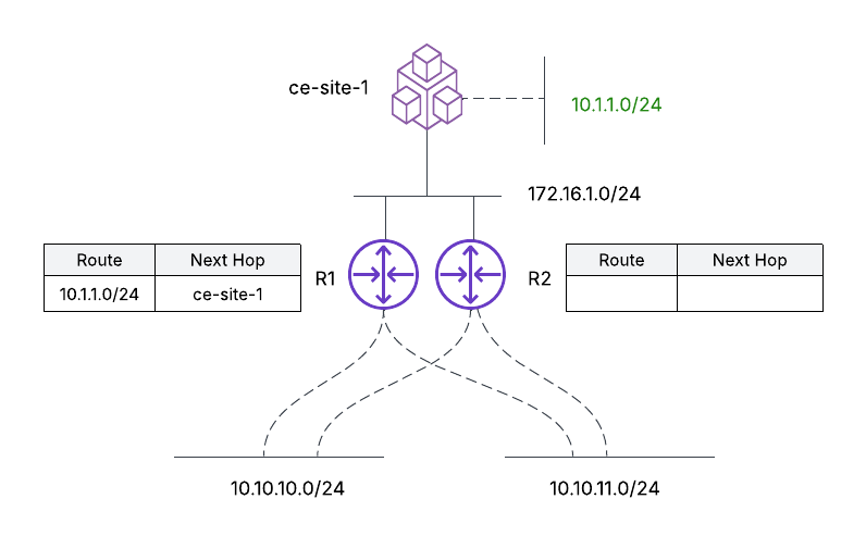
Figure: Outbound Route Filtering
- Outbound traffic engineering: The objective is to ensure that ce-site-1 chooses R1 as the exit point for all prefixes (10.10.10.0/24 and 10.10.11.0/24). This ensures that R2 is only used as a backup path if the link to R1 goes down.
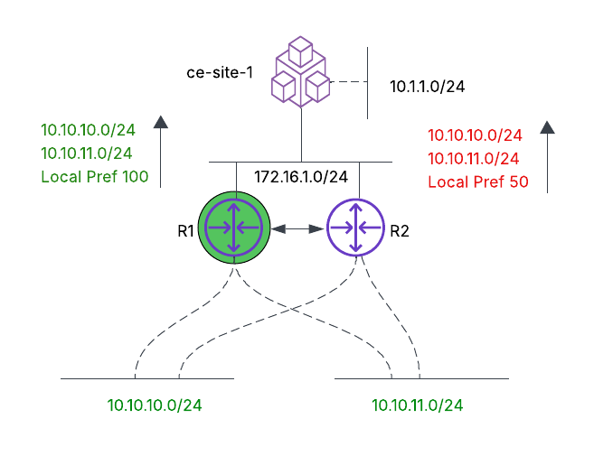
Figure: Outbound Traffic Engineering
- Inbound traffic engineering: The objective is to ensure that R1 and R2 choose the path between R1 and ce-site-1 for the prefix 10.1.1.0/24. Therefore, even for R2 to reach 10.1.1.0/24, it will traverse through R1 to reach 10.1.1.0/24.
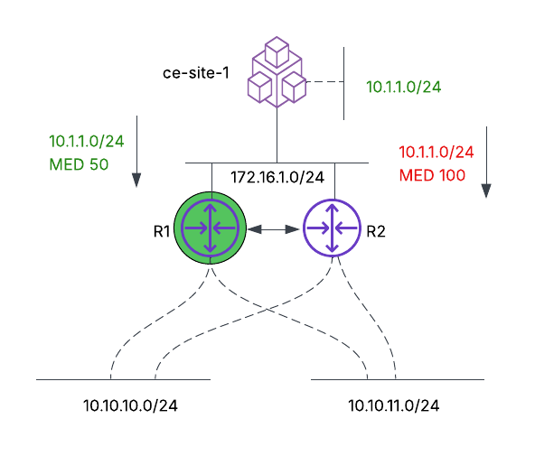
Figure: Inbound Traffic Engineering
-
Unsupported scenario: This scenario involves a multi-node CE Site (ce-site-1) with the objective to ensure that all nodes in the CE Site prefer Node 1 as the exit point, without full mesh peering from each node to each router.
- Node 1 peers with R1 and sets the routing policy to match the prefixes 10.10.10.0/24 and 10.10.11.0/24 and set the local preference to 100.
- Node 3 peers with R2 and sets the routing policy to match the prefixes 10.10.10.0/24 and 10.10.11.0/24 and set the local preference to 50.
The prefixes propagate within the CE Site (among nodes 1, 2, and 3). However, the BGP metrics will not propagate among the nodes. Therefore, the intent of choosing R1 as the exit point will not be honored. For this scenario to work today, you need to configure BGP peering from each node to R1 and R2, with an associated routing policy that prefers R1, for example. In this scenario, the decision becomes a local decision on the node and does not rely on route propagation between nodes within a CE Site.
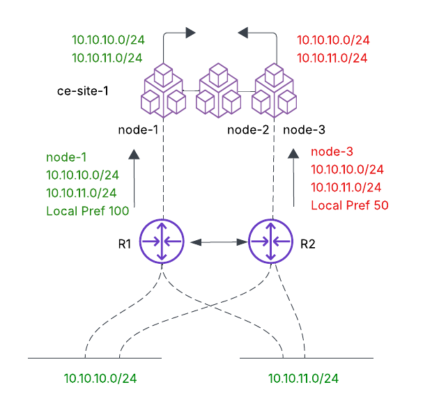
Figure: Unsupported Scenario
Configure BGP Routing Policies
Step 1: Provide metadata.
-
Navigate to Multi-Cloud Network Connect > Manage > Networking > BGP Peers and Policies.
-
Select the BGP Routing Policies tab and click Add BGP Routing Policy.
-
In the Name field, provide a name that reference the objective behind the policy and where it applies to.
-
Add Labels to help organize and categorize objects as per your preferences. Labels are not mandatory.
-
Optionally, add a Description to explain the full context behind the BGP routing policy.
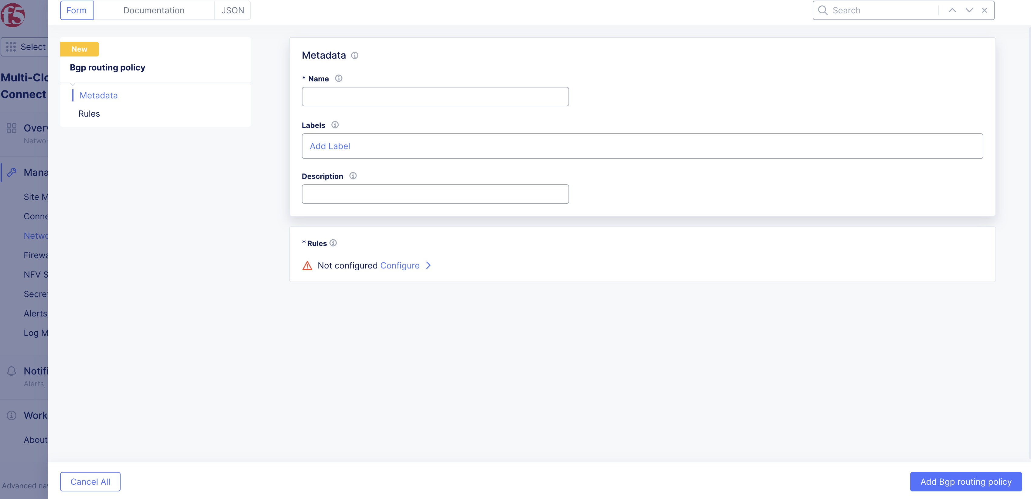
Figure: Add New Policy
Step 2: Configure rules.
A BGP routing policy consists of rules. These rules are processed in order from top to bottom. Each rule has a Match and an Action that you configure.
-
In the Rules section, click Configure and then Add Item to add a rule.
-
From the Type of Match drop-down menu, select an option:
- Prefix: This is the most common pattern of matching. When you choose Prefix, you need to add a Prefix List.
- BGP Community List: This option matches the prefix for BGP communities. At certain times, your BGP peer might send you prefixes and tag them with certain communities. You can use communities that choose all prefixes of 65000:100, for example.
- AS path to match: This option matches the prefixes for AS paths.
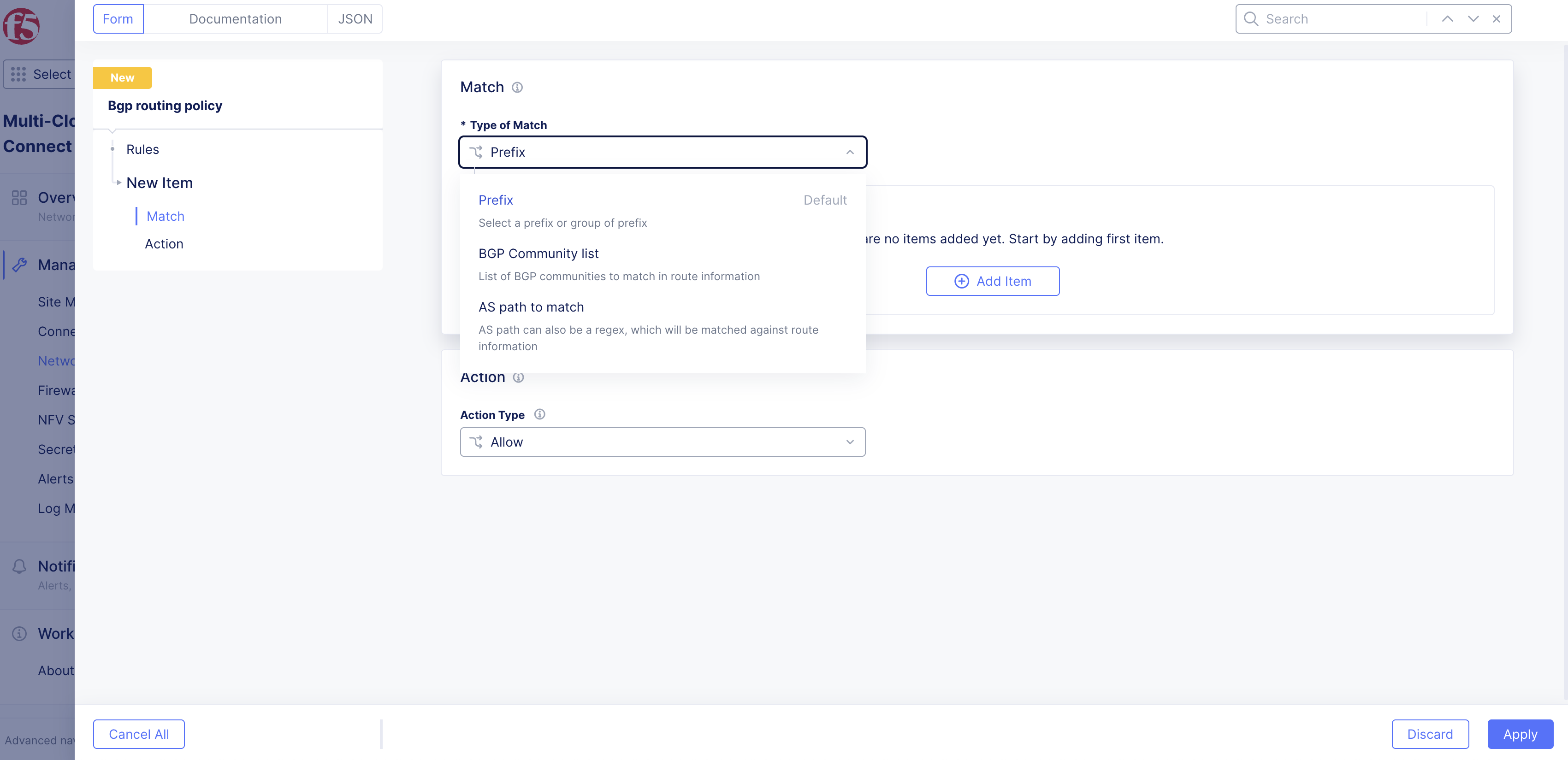
Figure: Match Menu Options
Step 2.1: Configure prefix rule.
-
From the Type of Match drop-down menu, select Prefix.
-
Click Add Item.
-
In the IP Prefix field, enter the prefix to match on. For example, 10.1.1.0/24.
-
From the Prefix length match drop-down menu, select an option:
- Exact Match: If the IP prefix is set to 10.1.1.0/24 and the Prefix length is Exact Match, you only match on 10.1.1.0/24.
- Equal or Longer than: This option matches multiple prefixes with a single statement. If the IP Prefix is set to 10.1.1.0/20, it encompasses a range from 10.1.0.0 to 10.1.15.255. Any prefix in the routing table that falls within this range is matched. For example, 10.1.2.0/24 and 10.1.3.0/24. Since you have the equal as part of the Prefix Length match, it also matches the prefix 10.1.1.0/20.
- Longer than: This option matches multiple prefixes with a single statement. This is very similar to Equal or Longer than. However, it does not match the prefix itself. In other words, if you choose Longer than 10.1.1.0/20 then 10.1.2.0/24 and 10.1.3.0/24 are selected but 10.1.1.0/20 is not selected.
-
Click Apply.
Step 2.2: Configure BGP community list.
-
From the Type of Match drop-down menu, select BGP Community List.
-
Enter the community value. For example, 65000:100.
Step 2.3: Configure AS path matching.
-
From the Type of Match drop-down menu, select AS path to match.
-
Enter the path value to match on.
Step 3: Configure the action type.
After you configure the match criteria, you must configure an action to take when the match criteria hits.
- From the Action Type drop-down menu, select an option:
- Deny: Generally used to reject the routes that are matched.
- Allow: Generally used to accept the routes that are matched.
- BGP Community list: Tags the specific routes in the match selection with a specific BGP community.
- MED/Metric: Multi-Exit Discriminator (MED) is generally used to influence inbound traffic to an AS. It is generally applied outbound toward the BGP peer to influence inbound traffic to the CE. When specifying MED, you need to provide the value for MED. Note that a lower MED actually wins.
- Local preference: Generally used to influence outbound traffic from an ASN. It is generally applied inbound from the BGP peer to influence outbound traffic from the CE. When selecting Local preference, you need to set the value for it. Note that a higher value wins.
- AS-path to prepend: Like MED, this option is used to influence inbound traffic to the CE. It is generally applied outbound toward the BGP peer to influence inbound traffic to the CE. When selecting this option, you need to prepend a possible value, such as 65001, 65001, or 65001. Note that the shorter as-path wins.
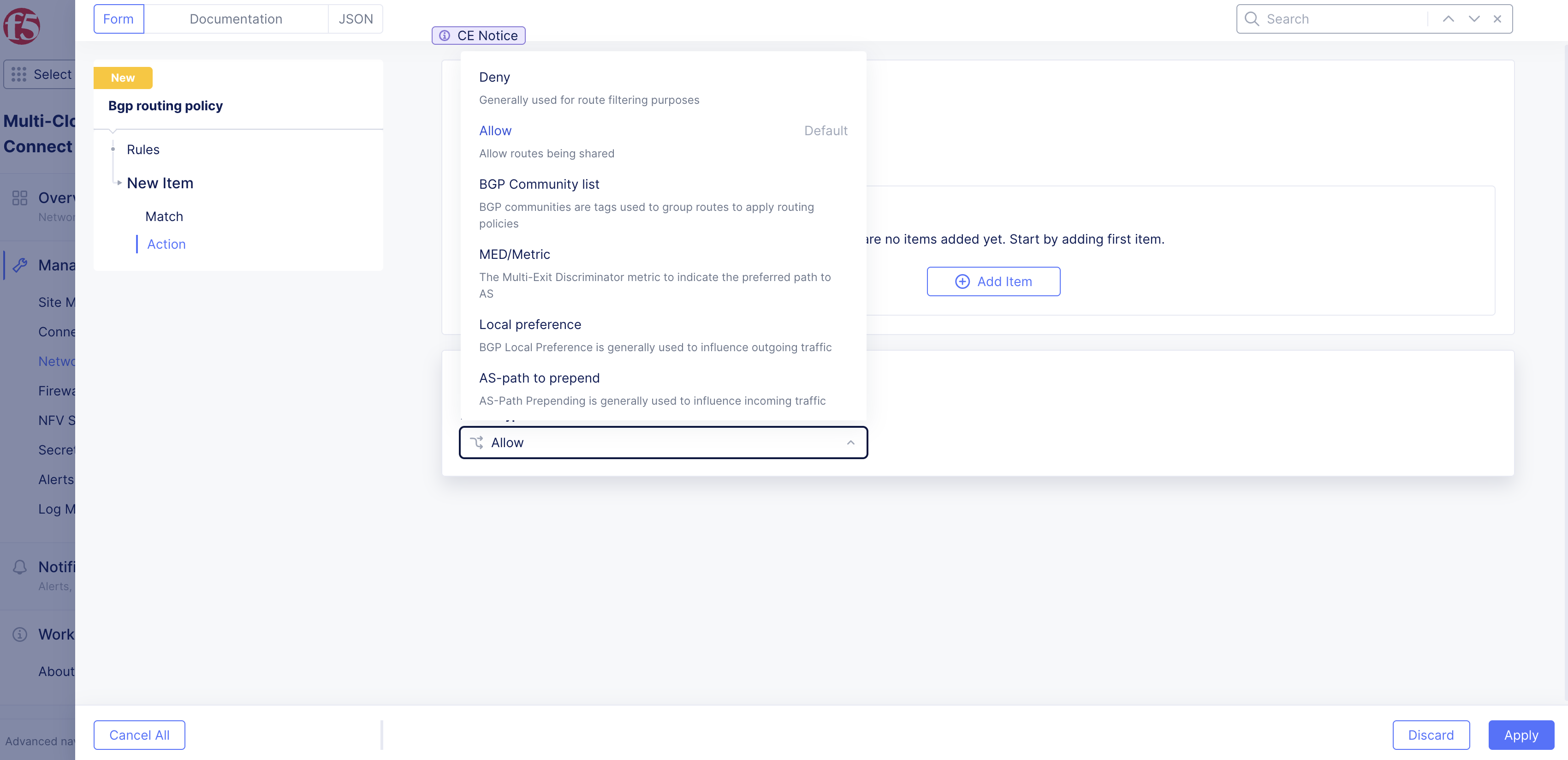
Figure: Action Type Options
- Click Apply.
Step 4: Complete rule configuration.
-
Click Apply.
-
Click Add BGP routing policy.
Apply BGP Routing Policies
You must apply BGP routing policies to a particular peer. When you apply the policy to a peer, you also must define the policy direction as inbound or outbound.
-
Navigate to the peer under the BGP Peers tab.
-
For your peer object, select ... > Manage Configuration > Edit Configuration.
-
Under the Peers section, click Add Item.

Figure: Peers Section
-
From the BGP Routing policy drop-down menu, select Enabled.
-
Click Add Item.
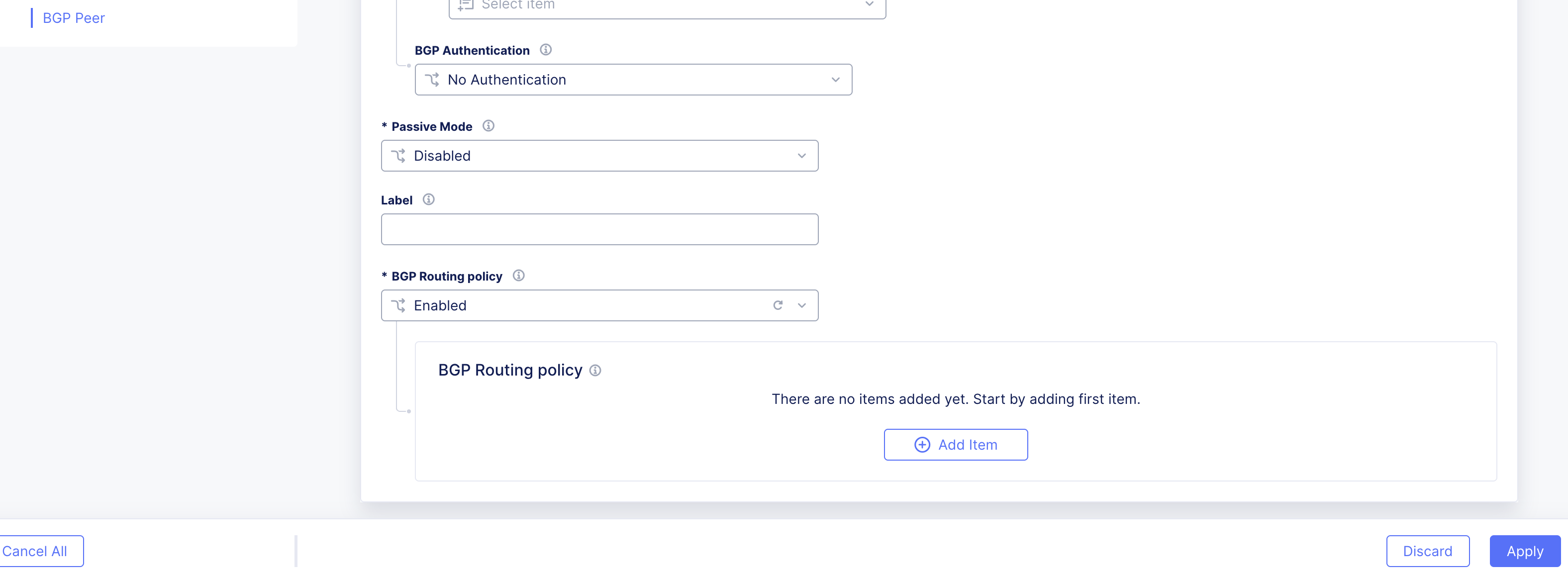
Figure: Policy Section
-
From the BGP routing policy drop-down menu, select the previously created policy.
-
From the Direction drop-down menu, select the route policy. Choose from Inbound or Outbound.
-
From the Applies to drop-down menu, select whether to apply the policy to all nodes of your CE Site or to a specific node. For specific nodes:
- Select Node name.
- Click Add Item.
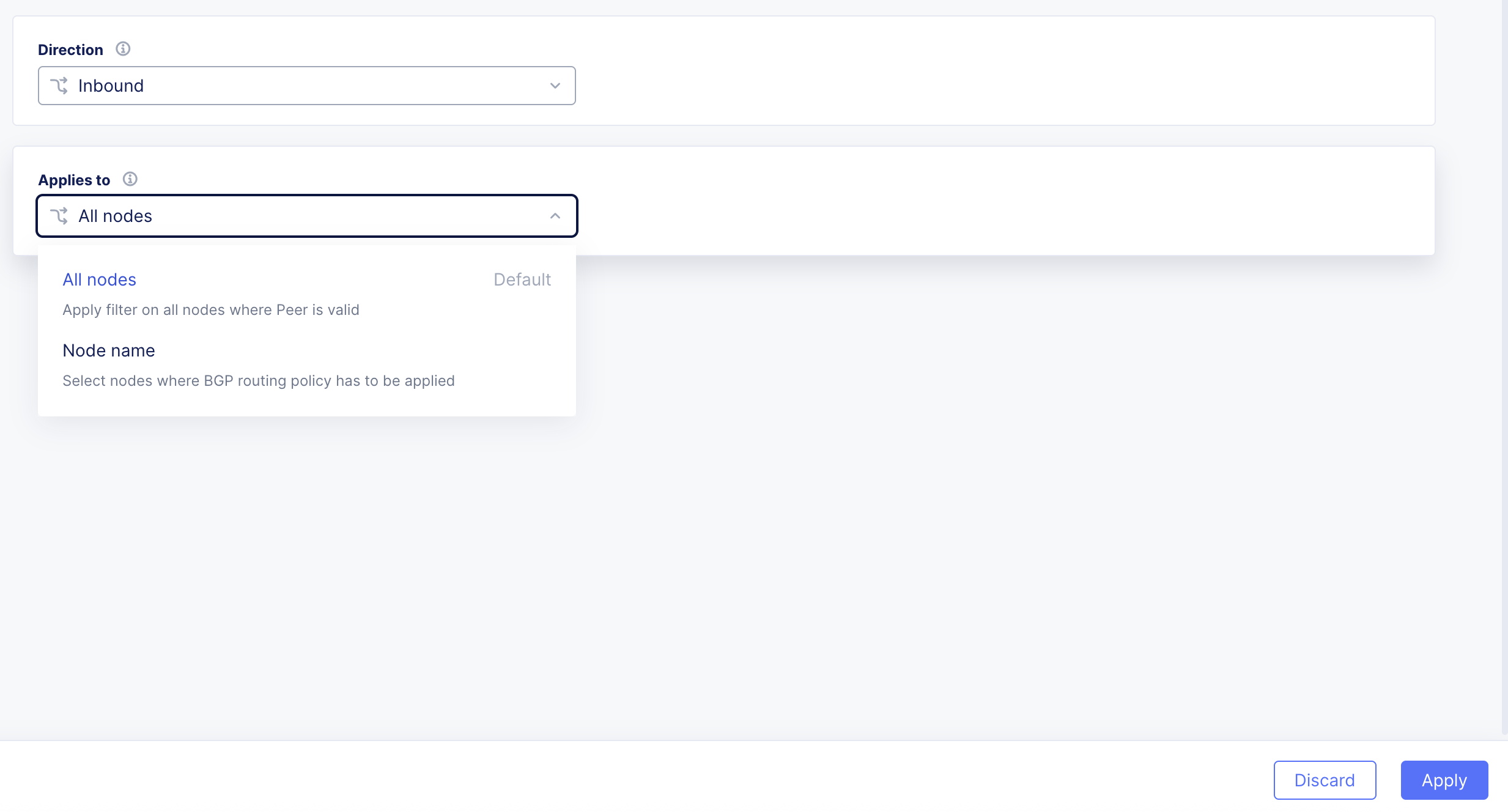
Figure: Menu Options
- From the Node of choice drop-down menu, select the node.
- To add another node, click Add Item again and select the node.
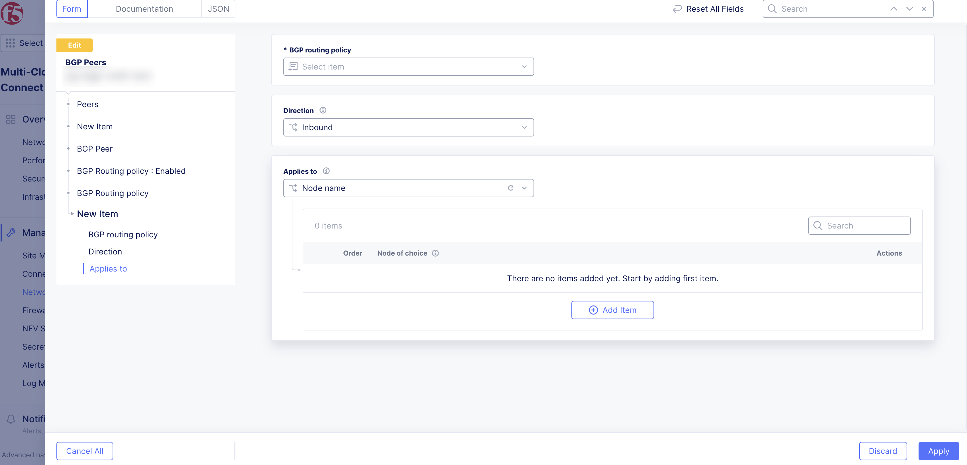
Figure: Select Node
-
Click Apply.
-
Click Apply.
-
Click Save BGP Peers.